Note :
Interface in firmware is optimized for 4.2' displays with 400x300 resolution, implementation of support for other resolutions is possible, but requires optimization of interface and writing a driver for a specific display.
The firmware is partially compatible with 1.5' displays - the interface output adapted for 200x200 resolution is implemented, you can output your own graphics, but such displays were not in priority and smaller versions of widgets & fonts suitable for the screen resolution were not ready yet. (default interface example)
see also List of supported displays
Setting Up the Development Environment (IDE)
To flash the firmware, you need to install Microsoft Visual Studio and the Platform IO extension.
- Download and install Microsoft Visual Studio
- Open Microsoft Visual Studio and select the Extensions section from the left sidebar (CTRL+SHIFT+X)
- Type "PlatformIO" into the search bar and select PlatformIO IDE (platformio.org) from the list
- Click Install and wait for the installation to complete, then restart Microsoft Visual Studio
Setting Up the Environment
- Download the latest firmware version from the Firmware and Tools section
-
Unzip the firmware into any directory and copy the external configuration into the "Volna42/platformio.ini" file if using ESP32
The platformio.ini file contains a configuration suitable for ESP8266 D1 Mini and similar boards. For the ESP32 microcontroller, you can rename or copy the configuration from the platformio.esp32.ini file
The ESP32 configuration is prepared for the YD-ESP32-23 - esp32-s3-devkitc-1 (ESP32S3, 8MB FLASH) board and may differ from what you need - this depends on the specific board/model of ESP32 - different models may differ in the number of pins as well as pin numbering and overall configuration.
If the configuration does not match, you can search for an example configuration on the PlatformIO website
-
Open Visual Studio and click the PlatformIO icon in the left control panel
Click Pick a folder and select the folder containing the platformio.ini file (Volna42 folder)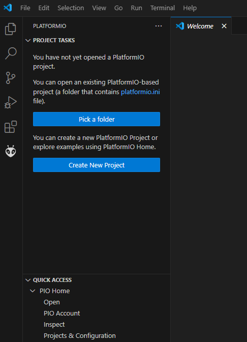
Configuration, Compilation, and Uploading Firmware
For initial testing, you can upload the firmware without connecting external modules (display, temperature sensor). See the assembly diagram for connecting the display and other options.
- Configure the settings in the UserDefines.h file
- Uncomment only the relevant define for your display type (see Displays)
#define WAVESHARE_BW_42_UC8176 WaveShare 4.2 BW rev 2.1 #define WAVESHARE_BW_42_SSD1683 WaveShare 4.2 BW 4-color grayscale rev 2.2
WeAct 4.2 BW#define WAVESHARE_RY_BW_42_UC8176 WaveShare 4.2 BW + Yellow rev 2.1 V2
WaveShare 4.2 BW + Red rev 2.1#define HELTEC_BW_15_S810F Heltec 1.5 BW
- Uncomment only the necessary define with the "BAT_" prefix depending on whether a battery is used - detailed comments for each option are provided in the UserDefines.h file
- Specify the pins (defines with the "EPD_") to which the E-Ink screen is connectedBy default, the "EPD_" pinout for ESP8266 is defined according to the diagram on the Schematics page and if using ESP8266 D1 Mini, you do not need to change anything.
-
Set connection settings, WiFi access in the UserSettings.h file. Explanations for the settings are provided in the file itself. Display settings can be configured later from web control panel.
Uncomment the appropriate lines based on the interface language of the weather station :Russian - #include <LocaleRu.h> #include <ui/out/locale_ru/locale.h>
English - #include <LocaleEn.h> #include <ui/out/locale_en/locale.h>
For security reasons, it is not necessary to explicitly specify your home WiFi network settings in the settings file as the device by default creates an access point if no settings are present or the WiFi network is incorrectly specified
Default access point
SSID : VOLNA42-EINK, password : volnaaccess
By connecting to this access point and going to http://192.168.1.1/, you can set your WiFi network settings for correct time auto-detection and sensor data synchronization.
-
If you make changes to the web interface files (folder _uiTools\uiEink), you must run the bat file before compiling the firmware :
minify_einkdisplay.bat - for Windows (check the _uiTools\htmlpack subfolder to compile the packer tool by yourself, or download binary - can be marked as unsafe by antivirus)
minify_einkdisplay.sh - for Linux (check the _uiTools\htmlpack subfolder to compile the packer tool)
This updates the *.h files in the "Volna42\src\ui\out" folder with the contents of the html, js, css files of the web interface for loading them from the device's FLASH memory later -
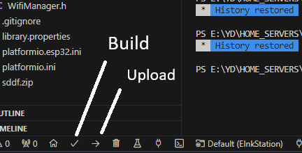
To compile and upload the firmware to the device - connect the ESP via USB
(the device must not have a battery connected at this time - provide a switch or perform the flashing through RX \ TX pins, via USB to TTL) and press the "Upload" button
-
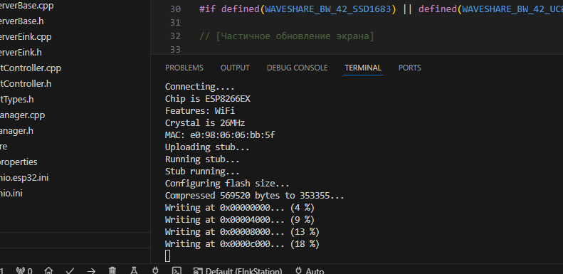
If the flashing process starts successfully, you will see the progress percentage
-
If after the flashing process the output does not switch to data (Serial Monitor), check manually and verify the outgoing data. If there is no data, restart the device using the RST button
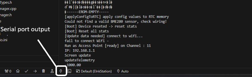
The screenshot shows output from a "bare" ESP with no external modules connected. The log shows that the temperature and humidity sensor could not be found, and WiFi connection data is not set, but the access point was successfully created
This information can also be useful during a full assembly if, for example, there is a contact issue with the sensor or connection errors. Connection errors can also be identified through the web control panel. -
If the firmware starts without issues, you can test with connected modules and continue configuration via the web interface. Due to specific of E-INK, if the display is very slow and during screen refresh (partial or full) slowdown web-panel navigation and requests, you can temporarily clear the screen and pause all events with the command http://[device IP]/api/clear and start events or screen refresh again with the command http://[device IP]/api/update.
If this is the battery version, temporarily turn off the BAT_SENSOR switch and restart the weather station (turn off \ turn on or press RST).
The weather station will then switch to continuous operation mode and display its IP address on the screen for further configuration.
After configuring, turn BAT_SENSOR back on and restart the device (via the web interface is fine) -> the device will return to power-saving mode
This is an optional integration setup. In this section, you will find information on how to connect the weather station to the smart home system so that it transmits its data from the BME280 sensor. It is assumed that you already have a server set up with an MQTT broker and a smart home control system - Domoticz or Home Assistant.
Sending weather station sensor data to Home Assistant
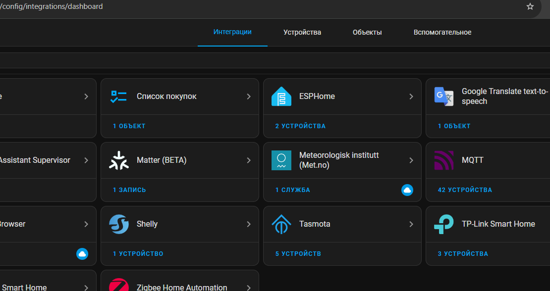
- Open the Home Assistant control panel (usually accessible at http://[server address]:8123)
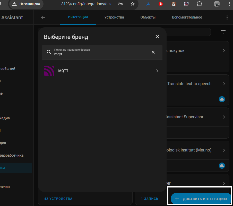
- Navigate to "Settings" -> "Devices & Services" (config/integrations/dashboard)

- If there is no integration with the MQTT broker, you need to set it up first through "Add Integration" -> MQTT
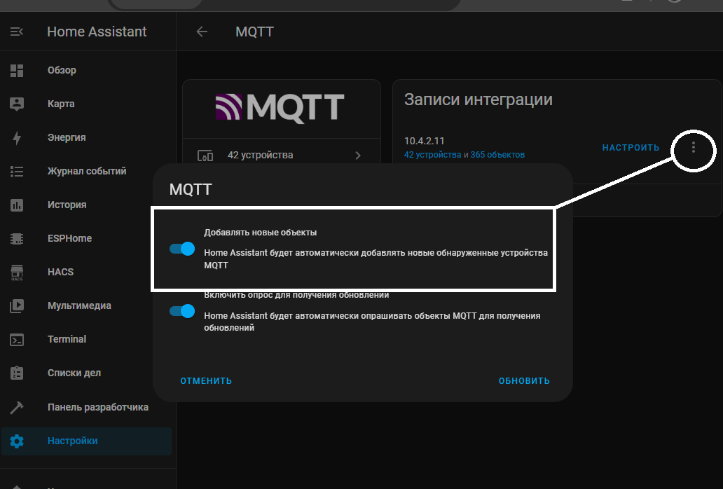
- In the integration settings, the option "Enable newly added entities (Home Assistant will automatically detect new devices...)" should be activated for automatic device detection
-
Go to the web interface page of the weather station - MQTT server -> click "Default options for Home Assistant". Override the Device id and Device name if necessary (try to keep the same length of names and IDs as the ability to send long strings is limited)
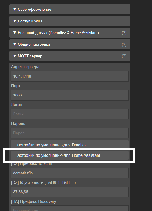
- Specify the address and port of the MQTT broker (by default login and password are not required, port is 1883)
- Click "Save changes" -> "Device control" -> "Reboot"
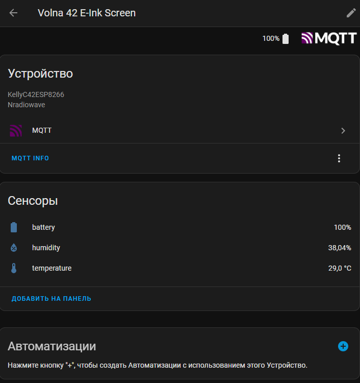
- After the reboot, if there were no errors, the MQTT status should change to "connected", and a new device should be added to the Home Assistant control panel in the list of MQTT devices according to the Device Name
Sending weather station sensor data to Domoticz
- Open the Domoticz control panel (usually accessible at http://[server address]:8080)
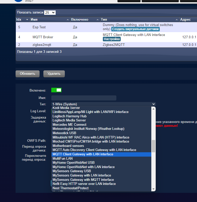
- Navigate to "Setup" -> "Hardware"
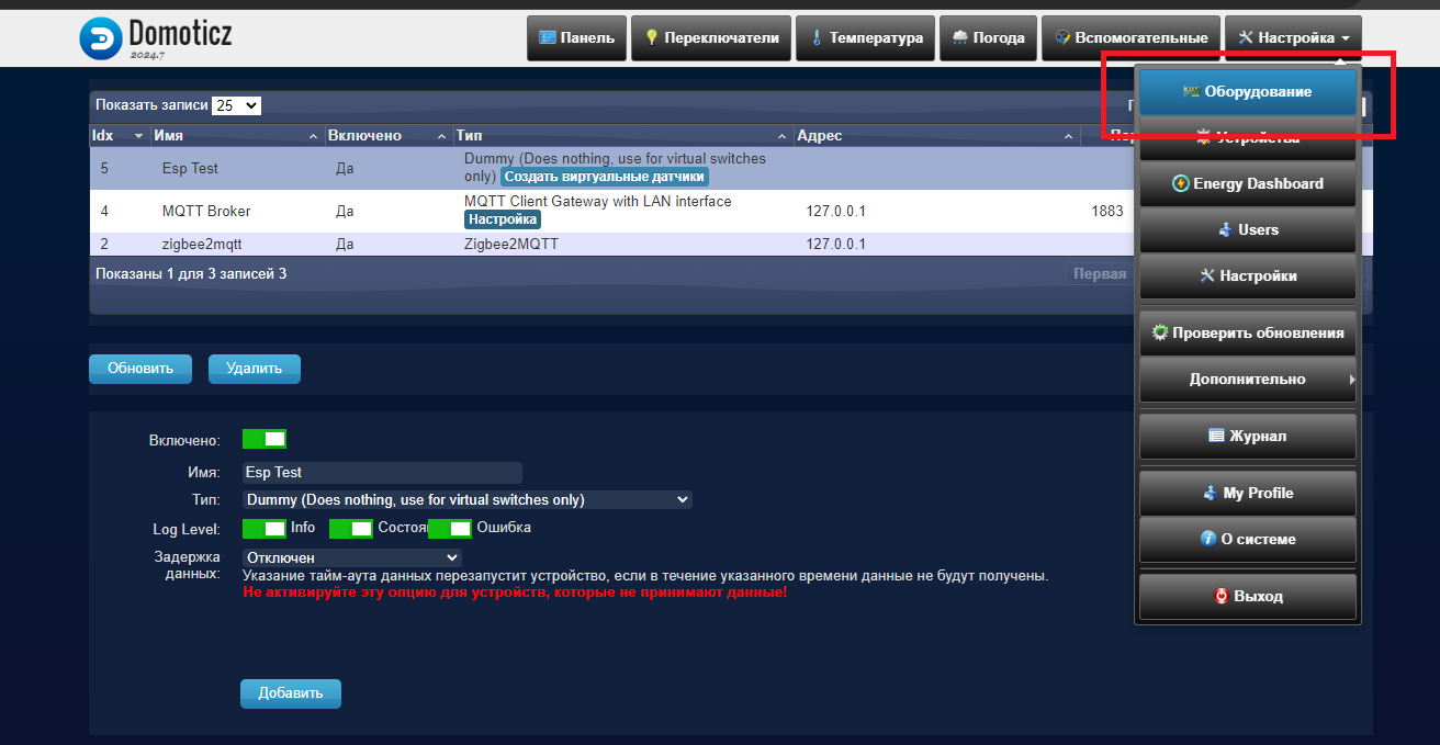
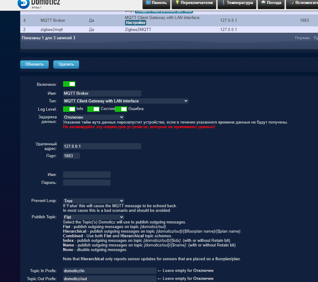
- If there is no "device" in the hardware list with the type "MQTT Client Gateway", you need to add it first (device creates connection between MQTT broker and Domoticz).
-
Check that settings match your configuration, when adding "MQTT Client Gateway". Usually if Domoticz and the MQTT broker installed on the same server default settings with localhost IP will be correct.
- If there is no device in the hardware list with the type "Dummy (Does nothing ...)", add it as well.
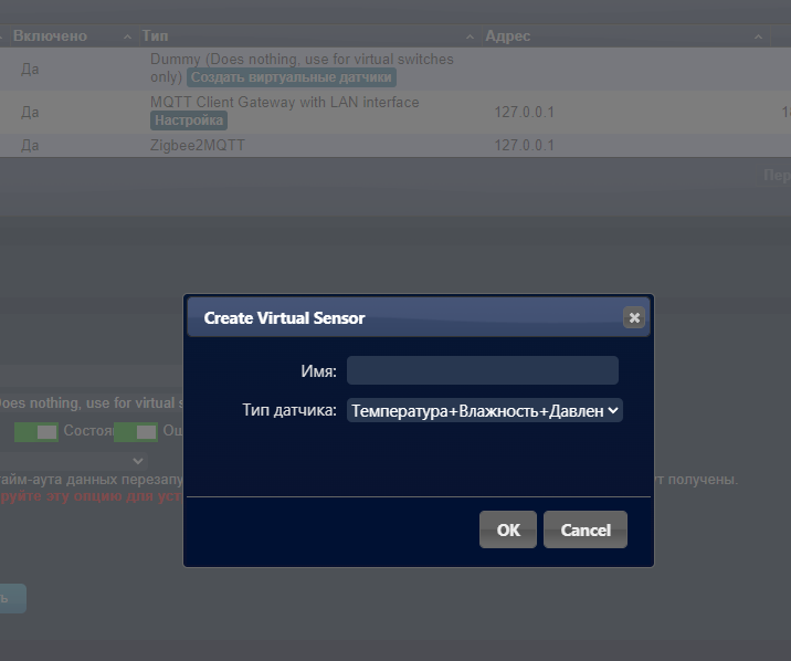
- After adding the "Dummy" device, click "Create Virtual Sensors"
- Add three virtual sensors with the sensor types "Temperature + Humidity + Barometer", "Temperature + Humidity", "Temperature"
- Write down their identifiers (Idx) from the page - "Setup" -> "Devices"
- Go to the web interface page of the weather station - MQTT server -> click "Default options for Domoticz"
- Enter the identifiers in order, separated by commas, in the "Device Ids (T&H&B, T&H, T)" field according to the type (1 - "Temperature + Humidity + Barometer", 2 - "Temperature + Humidity", 3 - "Temperature")
- Specify the address and port of the MQTT broker (usually, by default, login and password are not required, and the port is 1883)
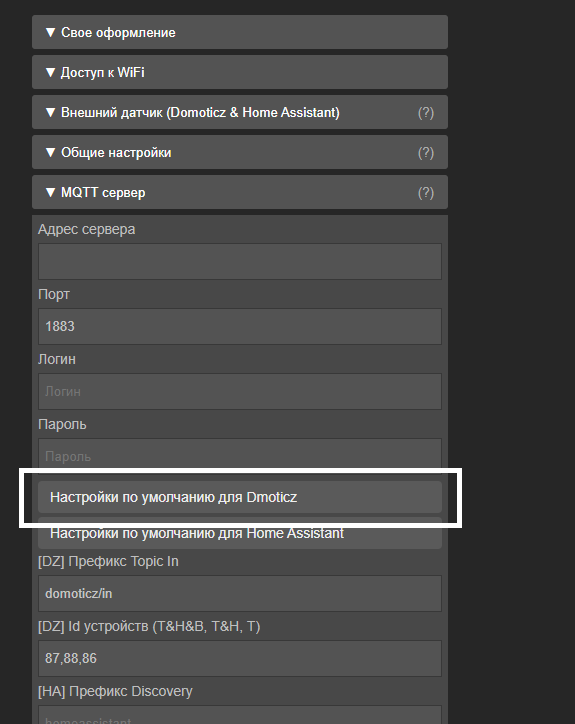
- Click "Save Changes" -> "Device Management" -> "Reboot"
- After the reboot, if there were no errors, the MQTT status should change to "connected", and the Domoticz control panel will start receiving data from the weather station and its sensors
Reading weather data from the OpenWeather service via API 2.5
- Available from firmware version >= 0.92
- Create an account on the OpenWeather service
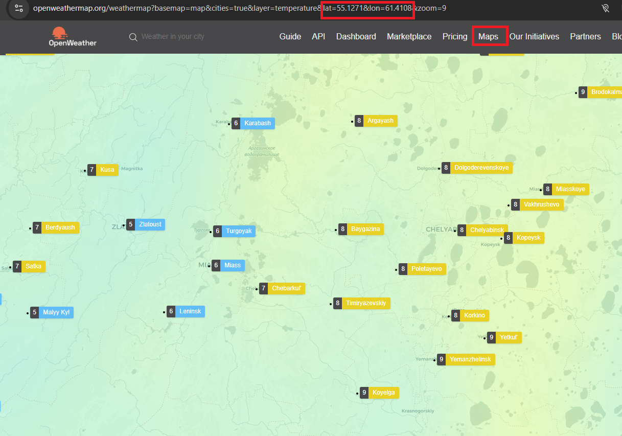
- Go to the "Maps" section and find the desired location
- Click on the location closest to your desired spot and copy the string like "lat=23.5556&lon=33.2797"
- After register new account - it can be activated only after few hours, so API can be unavailable during this time - information from OpenWeather
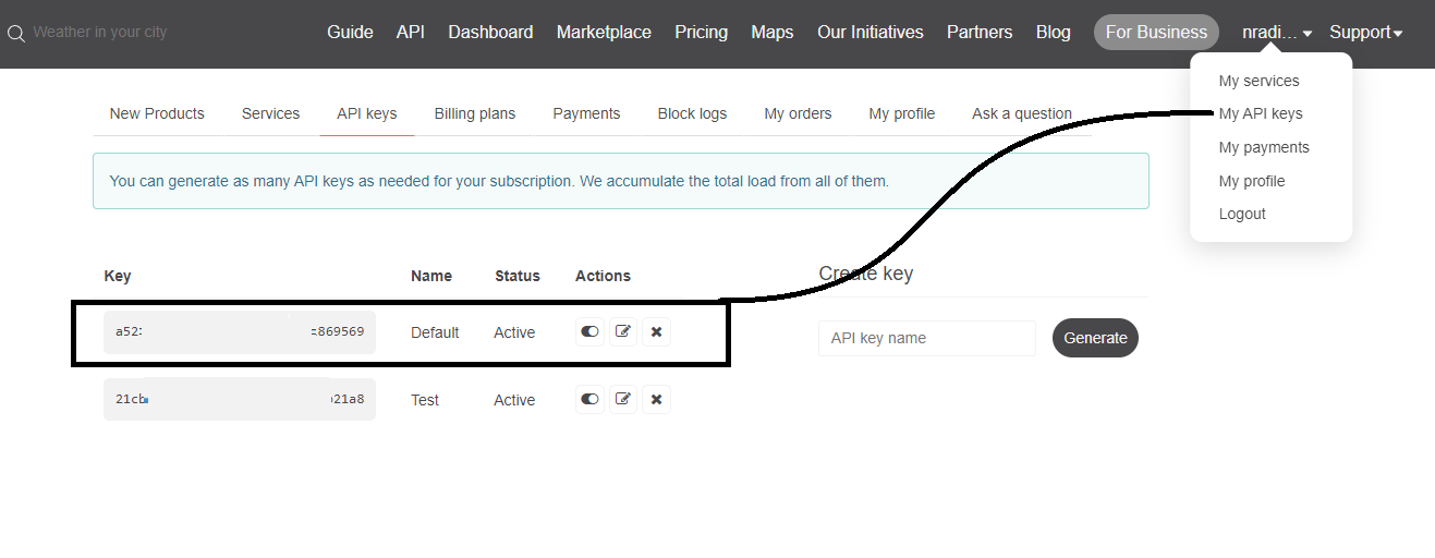
- Go to the API keys section in your account and copy the access key
- Insert the access key and location coordinates into the URL string http://api.openweathermap.org/data/2.5/weather?[coordinates]&APPID=[key]&units=metric. The resulting URL should look like
http://api.openweathermap.org/data/2.5/weather?lat=23.5556&lon=33.2797&APPID=a52afa5sdfsdfddf569&units=metric
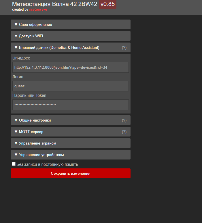
- Go to the web interface page of the weather station - "External sensor (Domoticz & Home Assistant)"
- Copy the resulting URL into the "URL address" field
- Leave the "Login" and "Password or Token" fields empty
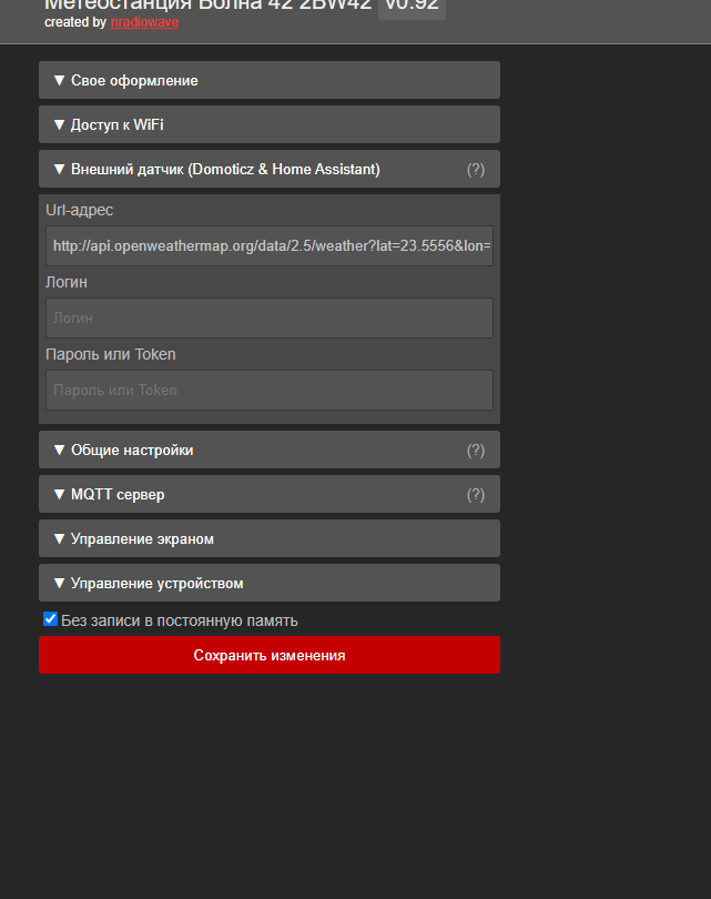
- Click "Save changes" -> "Device management" -> "Reboot" or "Device management" -> "Refresh screen"
- After rebooting, if everything went well, the status of "External sensor" should change to "connected," and the date of the last successful data sync will be displayed. If something went wrong, an error will be visible in the notifications block and logs.
Read external sensor data from Home Assistant on weather station
- Open the Home Assistant control panel (usually accessible at http://[server address]:8123)
- Go to the "Settings" -> "Devices & Services" section (config/integrations/dashboard)
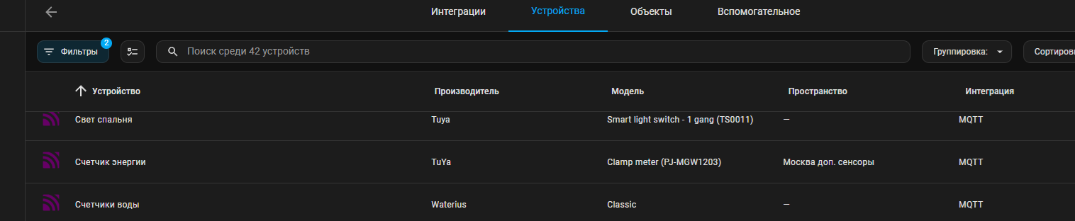
- Click on "Devices" under the "MQTT" integration
- Find the desired sensor in the list of devices
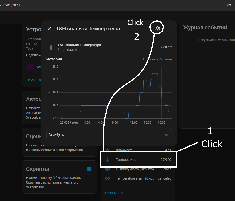
- Go to its configuration page, click on the sensor block. In the opened popup, click the gear icon in the top-right corner
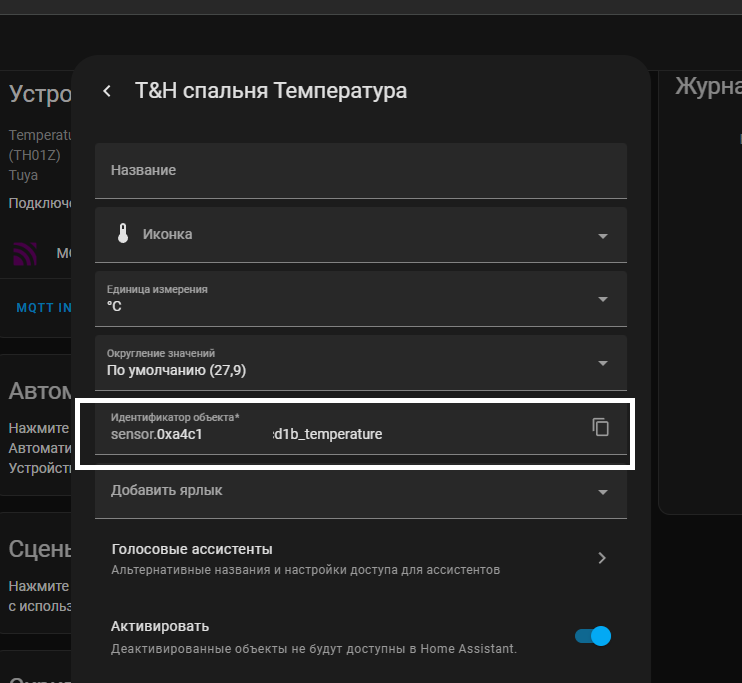
- In the opened editing form, find the "Object ID" of the form sensor.0xa4c1387jbj1a5dfgd1b_temperature
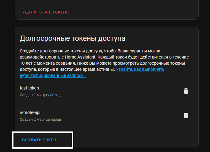
- If you do not have an authorization token for remote connections to Home Assistant, go to your account page in HA -> "Security" (/profile/security) and add a new token in the "Long-Lived Access Tokens" section and save the received key
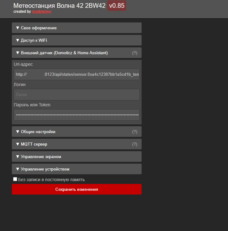
- Go to the weather station web interface page - "External Sensor (Domoticz & Home Assistant)"
- Enter the URL address as follows
http://[IP or server domain]:8123/api/states/[Object ID]
- Leave the "Login" field empty, and in the "Password or Token" field, enter the "Long-Lived Access Token"
- Click "Save Changes" -> "Manage Device" -> "Restart"
- After the restart, if everything went successfully, the "External Sensor" status should change to "connected" and the date of the last successful data synchronization will be shown. If something failed, an error will be visible in the notifications and logs
Read external sensor data from Domoticz on weather station
- Open the Domoticz control panel (usually accessible at http://[server address]:8080)
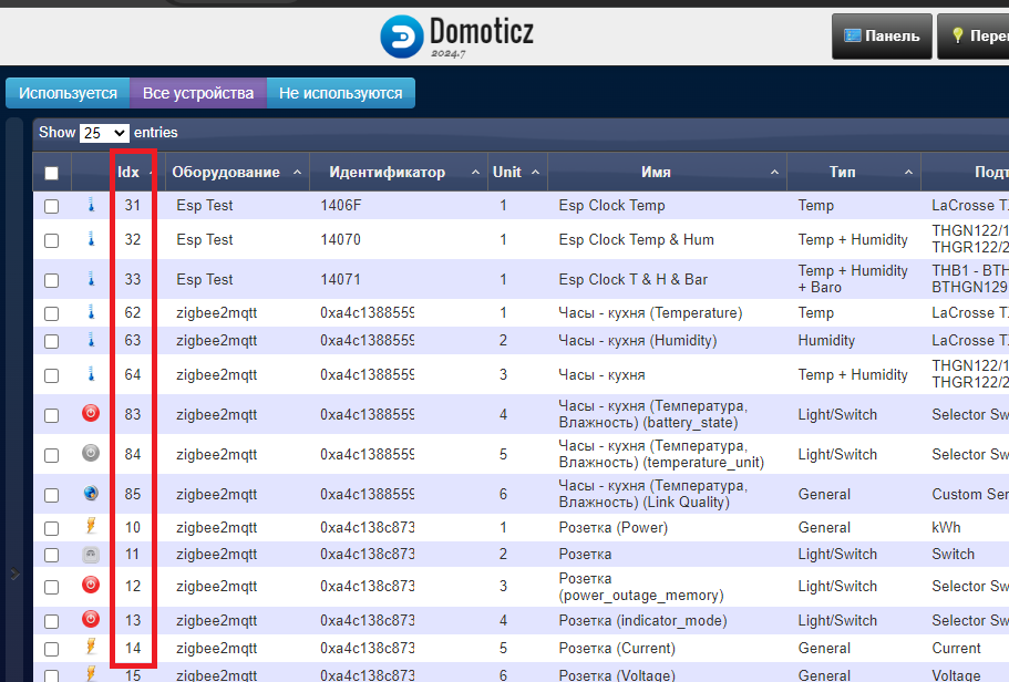
- Go to the "Setup" -> "Devices" section
- Find the desired temperature sensor and note the [Device ID] in the Idx field
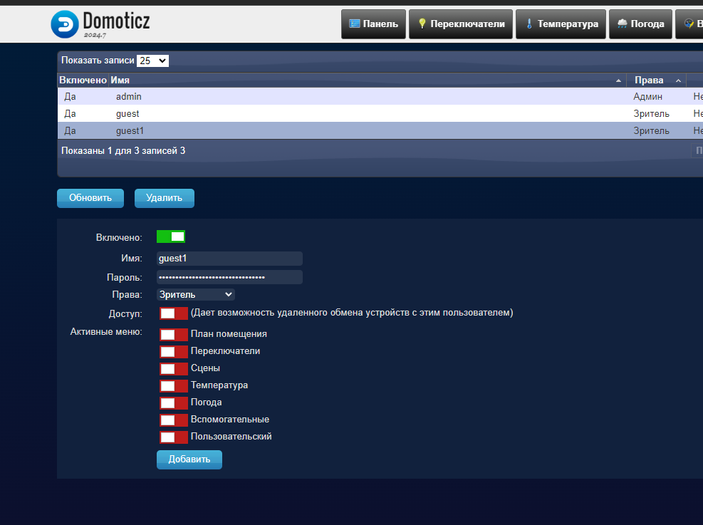
- Add a user for reading sensor data in the "Settings" -> "Users" section (set its rights to "Viewer")
- Go to the weather station web interface page - "External Sensor (Domoticz & Home Assistant)"
- Enter the URL address as follows
http://[IP or server domain]:8080/json.htm?type=devices&rid=[Device ID]
- In the "Login" and "Password or Token" fields, enter the credentials according to the user created in Domoticz
- Click "Save Changes" -> "Manage Device" -> "Restart"
- After the restart, if everything went successfully, the "External Sensor" status should change to "connected" and the date of the last successful data synchronization will be shown. If something failed, an error will be visible in the notifications and logs
Available REST API Methods
All requests should be made relative to the root URL path
Example request: Rebooting the device
// you need to execute the code from the device's web interface page.
var formData = new FormData();
formData.append("reboot", '1');
fetch("http://192.168.1.123/api/reboot", {method: 'POST', responseType: 'json', body: formData}).then(function(response) { console.log(response); });
Change the Image by Saved Style Name
GET /api/cui/select?filename=fairy
- filename - required parameter specifying the name of the saved style in the system
If the response includes reboot_required = true, to initiate a reboot perform
http://[device address]/api/update (GET) or http://[device address]/api/reboot?reboot=1 (POST)
Pause & Clear Screen
GET /api/clear
Clears the screen and pauses all events (partial and full screen auto-update) until the screen is manually refreshed through the control panel or until a full reboot
Update the Screen
GET /api/update
Reboot the Device
POST /api/reboot?reboot=1
- reboot - required parameter for confirmation
Clear Custom Styles Memory
POST /api/cui/format?confirm-format=1
- confirm-format - required parameter for confirmation
Reset System Settings
POST /api/reset?reset=1&reset-wifi=1
- reset - required parameter for confirmation
- reset-wifi - if specified, WiFi authorization data will also be cleared
Clear EEPROM Memory (Factory Reset)
POST /api/clearrom?confirm-clear=1
Completely clears the EEPROM memory (where all settings and WiFi authorization data are stored) and replaces the data with zero values.
- confirm-clear - required parameter for confirmation
Partial update clock area
POST /api/partialtest
Force partial update
ESP8266 does not come out of sleep mode
Some unofficial clones of D1 Mini boards may have the same problem. Check beforehand if pin D0 is correctly connected to the RST pin (for correct re-flashing it should be connected via a 510 ohm resistor, but for sleep mode tests just a jumper is enough).
The firmware provides several sleep modes for "cheap clones" case, different wakeup methods are defined in the UserDefines.h file by the FIX_DEEPSLEEP parameter. (if the parameter is not present, download the actual firmware from the main project branch at GitHub
Try setting the FIX_DEEPSLEEP parameter to 1 or 2 and check again. If the problem persists, the microcontroller is probably damaged or has more serious problems
Wrong date & time
By default weather station trying to sync time by NTP server. Device must be connected to WiFi hotspot with internet connections allowed.
If you sure that there is no any problem with internet connection, try to reboot device to reinit connection, or change NTP server in settings on any other
To reinit time without restart you can use this option (then after information about command successfull executed -> "Screen controll" -> "Refresh screen")
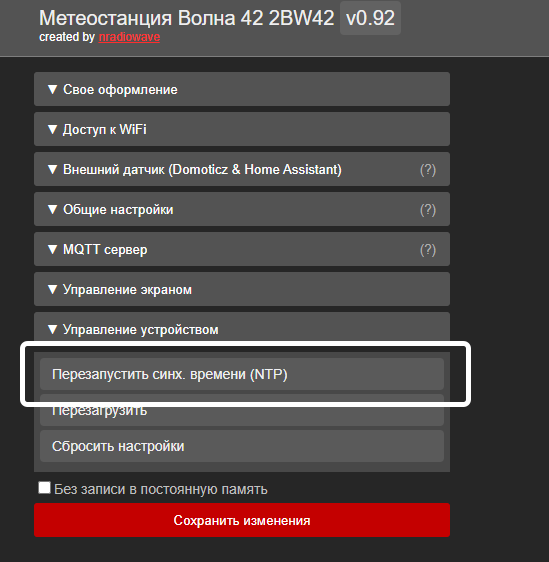
If you dont have internet connection, you can set time manually, by setting up "Date & Time" setting in "General options". Optionaly remove "Timezone" option to exclude additions time correction
Unable to upload firmware
Relevant for ESP8266
- [Battery & Deep Sleep mode version] Check that pin D0 (GPIO16) is connected to RESET through a resistor (should be around 510 Ohms), not directly.
- The device might not be entering the flashing mode - press the RST button on the device and try again.
- Check if the ESP is flashing properly by disconnecting all unnecessary connections and trying to flash with a minimal test example that outputs "Hello World" to the console.
- If the device is connected via RX/TX, make sure the device is in flashing mode (GPIO0 connected to GND) and GND is also connected to USB to TTL.
- Ensure that a COM device appears in the system when the ESP is connected. If the device is unrecognized, you need to install the usb driver for CH340 (usually) driver (could not find an official link, but this driver is usually auto-recognized in Windows 8-11). This is required for proper USB-UART functionality.
- Try manually selecting the required COM port (the "Auto" icon in the bottom panel of VS).
- There have been cases where the controller turned out to be defective - in same situation, one board flashed without issues while another just gave errors during flashing, and no amount of resetting helped.
Relevant for ESP32
- Check if the ESP is flashing properly by disconnecting all unnecessary connections and trying to flash with a minimal test example that outputs "Hello World" to the console.
- The device might not be entering flashing mode - press the RST button on the device and try again. You may need to hold down both RST + BOOT to activate UART mode (which might affect the detection of the COM device in the system).
- Ensure that a COM device appears in the system when the ESP is connected. If the device is unrecognized, you need to install the USB-CH340 driver (could not find an official link, but this driver is usually auto-recognized in Windows 8-11). This is required for proper USB-UART functionality.
- Try manually selecting the required COM port (the "Auto" icon in the bottom panel of VS).
Display shows nothing
If you are sure that the correct display type is selected in UserDefines.h (there are basically two options - displays with the SSD1683 prefix or UC8176 - no output will occur if the controller is incorrectly specified), it is likely that the pins are not connected correctly or there is a contact issue somewhere. Double-check that all pins are connected properly. If you are not sure if the ESP board itself is functional, try connecting display to another ESP board. You can check the functionality of the ESP or individual pins by writing a simple sketch implementing a button or LED blinking. But usually, if the ESP board is defective, problems would start during the flashing phase (either flashing intermittently or not at all). My issues were typically resolved by double-checking all pins and running some minimal examples from the manufacturer to confirm that the error was not in my code.
Display outputs information intermittently or adds unpredictable noise / artifacts
The contact for the BUSY pin might be faulty, or its defined wrong in UserDefines.h -> EPD_BUSY_PIN (e.g., it could be swapped with EPD_RST_PIN).
Display does not work in partial screen update mode
The manufacturer usually specifies whether this mode of operation is supported. Even if the display controller supports partial updates, it may not work if the board manufacturer does not claim it. Check examples provided by the manufacturer to see if there are methods for partial output.
ESP goes into infinite reboot loop after flashing firmware
- ESP32 The wrong device configuration might be selected in platformio.ini - you can check additional information in the terminal output when connected to the COM port. You can create an empty project and check minimal output with "hello world" to determine if the configuration is correct or not.
- Used nonexistent or invalid pins (considering the input signals from the display) in the UserDefines.h configuration.
If the issue persists consistently and no additional factors other than the connected display affect it and a complete power-off does not help, check which pin is causing this behavior and try reassigning what is connected to it to another pin.
I have tried using remaining pins, for example, for switches, and this led to similar issues since ESP8266 only has a few GPIO pins that are safe: GPIO14, GPIO12, GPIO13, GPIO4, GPIO5; all other pins should not be in a certain logical state at startup.
The pinout for connecting the display has been chosen to avoid disrupting the ESP's operation and it did not cause me problems when connecting different displays. However, it may not suit you if you find that the issue is specifically with the display connection (e.g., if a new, untested screen is used that outputs different signals).
Here is also an alternative pinout that I used earlier with pin D4 through a resistor. The device sometimes could hang after flashing and restarting via UART with different displays, but in normal operation, everything worked without problems.
#define EPD_RST_PIN 12 // D6 - GPIO - 12 (MISO)
#define EPD_DC_PIN 0 // D3 - GPIO - 0
#define EPD_CS_PIN -1 // GND (-1)
ESP Randomly Does Not Exit Deep Sleep
This happened with one ESP controller, it might have been defective, but after replacing the ESP board with another, the problem disappeared. In case ESP8266 you can also try to select different wakeup method in the UserDefines.h file by changing the FIX_DEEPSLEEP parameter.